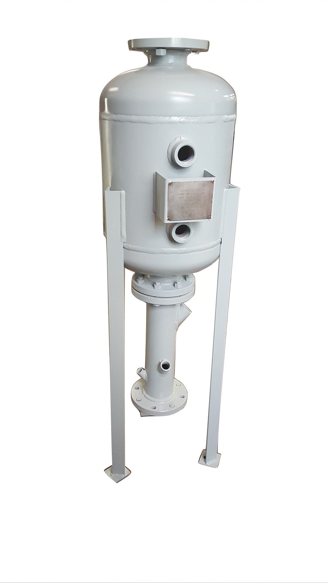
These heavy steel tanks receive the blowdown water from a boiler and cool it down using the flash steam principle, along with convection cooling over several hours for the retained hot water. The tank is designed to breakup the blowdown flow by impacting the high pressure hot water on the steel centrifugal impact plate. The water droplets give up heat as flash steam is formed. The flash steam is vented from the top of the tank to the atomsphere. Retained water displaces cooled water from the previous blowdown, and is retained in the tank until it cools to the statute limits.
Data required for sizing calculations: Blowdown pipe size, type and equivalent length to tank. Boiler steam drum diameter & length. Boiler operating pressure.
| Part # | Maximum PSI | Description Dia. x Height, inlet, drain, vent | |
|---|---|---|---|
| BD130A22 | 150 | 10' x 30", 3/4" NPT. 2-1/2" NPT, 2-1/2" NPT | Add to RFQ |
| BD130B23 | 150 | 10' x 30". 1" NPT, 2-1/2" NPT, 3" NPT | Add to RFQ |
| BD230C44 | 150 | 16' x 30", 1-1/4" NPT, 4" 150# Flg, 4" 150# Flg | Add to RFQ |
| BD230D45 | 150 | 16' x 30", 1-1/2" NPT, 4" 150# Flg, 5" 150# Flg | Add to RFQ |
| BD230E55 | 150 | 16' x 30", 2" NPT, 4" 150# Flg, 4" 150# Flg | Add to RFQ |
| BD242A34 | 300 | 16' x 42", 3/4" NPT, 3" 150# Flg, 4" 150# Flg | Add to RFQ |
| BD242B44 | 300 | 16' x 42", 1" NPT, 4" 150# Flg, 4" 150# Flg | Add to RFQ |
| BD242C45 | 300 | 16' x 42", 1-1/4" NPT, 4" 150# Flg, 5" 150# Flg | Add to RFQ |
| BD242D56 | 300 | 16' x 42", 1-1/2" NPT, 5" 150# Flg, 6" 150# Flg | Add to RFQ |
| BD242E68 | 300 | 16' x 42", 2" NPT, 6" 150# Flg, 8" 150# Flg | Add to RFQ |
| AC200 | - | 2-1/2" x 20", 2-1/2" NPT Inlet/drain, 3/4" NPT Cooling Water Inlet | Add to RFQ |
| AC300 | - | 3" x 20", 3" 150# Flg Inlet/drain, 1" NPT Cooling Water Inlet | Add to RFQ |
| AC400 | - | 4" x 20", 4" 150# Flg Inlet/drain, 1-1/4" NPT Cooling Water Inlet | Add to RFQ |
| AC500 | - | 5" x 20", 5" 150# Flg Inlet/drain, 1-1/2" NPT Cooling Water Inlet | Add to RFQ |
| AC600 | - | 6" x 20", 6" 150# Flg Inlet/drain, 1-1/2" NPT Cooling Water Inlet | Add to RFQ |
| AC800 | - | 8" x 20", 8" 150# Flg Inlet/drain, 2" NPT Cooling Water Inlet | Add to RFQ |
| AC101 | 250 | Temperature Regulating Valve, self op, Bronze 1/2" | Add to RFQ |
| AC102 | 140 | Temperature Regulating Valve, self op, Bronze 3/4" | Add to RFQ |
| AC103 | 250 | Temperature Regulating Valve, self op, Bronze 1" | Add to RFQ |
| AC104 | 250 | Temperature Regulating Valve, self op, Bronze 1-1/4" | Add to RFQ |
| AC105 | 250 | Temperature Regulating Valve, self op, Bronze 1-1/2" | Add to RFQ |
| AC106 | 250 | Temperature Regulating Valve, self op, Bronze 2" | Add to RFQ |
| HX012A | Temperature Gauge, 2" Dial | Add to RFQ |
| Part # |
Description Diameter x Shell Length x OAH, vent, drain |
Price Description |
A Measurement |
B Measurement |
C Measurement |
D Measurement |
E Measurement |
F Measurement |
|
|---|---|---|---|---|---|---|---|---|---|
| BD3600 | 36" x 30" x 70", 4", 3" | CALL FOR PRICING! | 30" | 2" | 4" | 3" | 2" | 70" | Add to RFQ |
| BD4200 | 42" x 42" x 85", 5", 3" | CALL FOR PRICING! | 42" | 2" | 5" | 3" | 2" | 85" | Add to RFQ |
| BD4800 | 48" x 48" x 94", 6", 4" | CALL FOR PRICING! | 48" | 2" | 6" | 4" | 2" | 94" | Add to RFQ |
| BD5400 | 54" x 66" x 116", 6", 4" | CALL FOR PRICING! | 54" | 2" | 6" | 4" | 2" | 116" | Add to RFQ |
| BD6000 | 60" x 72" x 125", 6", 4" | CALL FOR PRICING! | 60" | 2" | 6" | 4" | 2" | 125" | Add to RFQ |
| BD7200 | 72" x 96" x 155", 10", 4" | CALL FOR PRICING! | NA | NA | NA | NA | NA | NA | Add to RFQ |
| Item | Description | |
|---|---|---|
| #1 | __" NPTF Blowdown Inlet Connection | Add to RFQ |
| #2 | __" Vent Connection, 150 psi RF Flange | Add to RFQ |
| #3 | __" Drain Connection. 150 psi RF Flange | Add to RFQ |
| #4 | 2" NPTF Inspection Opening | Add to RFQ |
| #5 | Impingement Plate, Stainless Steel | Add to RFQ |
| #6 | Wall Baffle, Stainless Steel | Add to RFQ |
| #7 | Spiral Baffle, Stainless Steel | Add to RFQ |
| #8 | Legs with Foot Pad | Add to RFQ |
| #9 | Foot Pad | Add to RFQ |
| #10 | Vessel Height: ___30", ___42" | Add to RFQ |
| Part # | Pressure | Aftercooler Part No. F | Cold Water Inlet Size | Aftercooler Size | Regulating Valve Number | Valve Size G | |
|---|---|---|---|---|---|---|---|
| BD130A22 | Up To 150 PSI | AC200 | 3/4" | 2-1/2" NPT | AC102 | 3/4" | Add to RFQ |
| BD130B23 | Up To 150 PSI | AC200 | 3/4" | 2-1/2" NPT | AC102 | 3/4" | Add to RFQ |
| BD230C44 | Up To 150 PSI | AC400 | 1-1/4" | 4" NPT | AC104 | 1-1/4" | Add to RFQ |
| BD230D45 | Up To 150 PSI | AC400 | 1-1/4" | 4" NPT | AC104 | 1-1/4" | Add to RFQ |
| BD230E45 | Up To 150 PSI | AC400 | 1-1/4" | 4" NPT | AC104 | 1-1/4" | Add to RFQ |
| BD242A34 | Up To 300 PSI | AC300 | 1" | 3" NPT | AC103 | 1" | Add to RFQ |
| BD242B44 | Up To 300 PSI | AC400 | 1-1/4" | 4" NPT | AC104 | 1-1/4" | Add to RFQ |
| BD242C45 | Up To 300 PSI | AC400 | 1-1/4" | 4" NPT | AC104 | 1-1/4" | Add to RFQ |
| BD242D56 | Up To 300 PSI | AC500 | 1-1/2" | 5" NPT | AC105 | 1-1/2" | Add to RFQ |
| BD242E68 | Up To 300 PSI | AC600 | 1-1/2" | 6" NPT | AC105 | 1-1/2" | Add to RFQ |
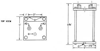
| Part # | Pressure | Blowdown Inlet A | Drain B | Vent C | Vessel Diameter D x Height E | |
|---|---|---|---|---|---|---|
| BD130A22 | Up To 150 PSI | 3/4" | 2-1/2" | 2-1/2" | 10" x 30" | Add to RFQ |
| BD130B23 | Up To 150 PSI | 1" | 2-1/2" | 3" | 10" x 30" | Add to RFQ |
| BD230C44 | Up To 150 PSI | 1-1/4" | 4" | 4" | 16" x 30" | Add to RFQ |
| BD230D45 | Up To 150 PSI | 1-1/2" | 4" | 5" | 16" x 30" | Add to RFQ |
| BD230E45 | Up To 150 PSI | 2" | 4" | 5" | 16" x 30" | Add to RFQ |
| BD242A34 | Up To 300 PSI | 3/4" | 3" | 4" | 16" x 42" | Add to RFQ |
| BD242B44 | Up To 300 PSI | 1" | 4" | 4" | 16" x 42" | Add to RFQ |
| BD242C45 | Up To 300 PSI | 1-1/4" | 4" | 5" | 16" x 42" | Add to RFQ |
| BD242D56 | Up To 300 PSI | 1-1/2" | 5" | 6" | 16" x 42" | Add to RFQ |
| BD242E68 | Up To 300 PSI | 2" | 6" | 8" | 16" x 42" | Add to RFQ |
| Part # | Coil Material | Coil Surface Area | Coil Rating PSI | |
|---|---|---|---|---|
| SC0005 | Copper | 1.2 | 300 | Add to RFQ |
| SC0006 | 316 SS | 1.2 | 1,200 | Add to RFQ |

© 2024 Boiler Supplies. All Rights Reserved. |


 Back to Products